
Understanding IT Networks. It’s not about information technology
Mark Smith CEng, CMarEng, FIMarEST, BAppSc(MarEng) Engineering Surveyor Accredited Marine Surveyor: AMSA – 3242-6148 4 Qld EC lic. 73995 Authorised Maritime NZ Surveyor – SRV242
Understanding the distinction between an AC electrical network isolated from the earth, which is an IT installation, and the commonly used TN-S (Terre Neutral – Separated) network, which is generally used on DCV vessels, is crucial (Fig. 1:). This knowledge will enable you to make informed decisions and ensure the fundamental safety of the electrical installation is met when working on, designing, or approving a drawing.
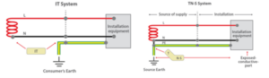
Fig. 1: IT and TN-S Network Installations
The use of IT installation is acceptable within Australia and is detailed within the following Standards:
- AS/NZS 3004.2 – Electrical installations Part 2: Boat installations.
- AS/NZS 3007 – Electrical equipment in mines and quarries, surface installations, and associated processing plant.
This type of electrical installation is common for ships, as it allows equipment to operate with an earth fault to increase continuity of service. The best example of why this is so important is for steering gear, as tripping due to an earth fault is to be avoided, particularly when maneuvering is restricted.
Another significant advantage of IT installations is their practical and economical nature. By eliminating the need for a neutral wire (3-wire network), they reduce associated costs, making them a practical and economical choice for ship electrical systems. It’s important to note that a 4-wire network can also be an IT installation.
Dealing with an IT network requires a level of exposure and experience that only comes with time. This understanding is crucial when dealing with an above-earth network, as it’s easy to fall into the mindset of a TN-S, also referred to as a Multiple Earth Neutral (MEN) Network. While the fundamentals are the same, there are specific safety requirements that must be understood and met for an IT network to ensure safe operation.
However, over the past six weeks, I noticed some serious misunderstandings of how an IT network is meant to operate safely. This happened because a couple of vessel owners engaged me regarding their electrical installation, and both provided DCV-approved electrical plans for reference.
In both cases, a common theme was present: the principles of a TN-S network were applied instead of those required for an IT network.
What has been missed was the consideration of the fundamental principle of IT networks, which is that of a First Fault Condition and safety requirements that shall be available:
- Permanent monitoring of the insulation to detect a First Fault to Earth occurrence and alarm.
- For a 4-wire system, a device limiting the voltage the neutral can supply and reach the Earth.
- In a Second Fault to Earth occurrence, the appropriate circuit breakers shall trip.
Unlike a TN-S network that trips protective devices on a First Fault, an IT network will alarm on a First Fault, and it is important to have a process for identifying the fault location and rectifying it before a Second Fault occurs.
It is to be understood that one system is no safer than the other, as both can cause fire, electrocution or death. Both require specific safety devices and monitoring to manage the risk when designing and approving installation schematics.
With this article, I hope to pass on some knowledge of the identified safety issues associated with both these cases and provide a summary of safety issues caused by applying the wrong fundamental principles to an IT network about the design of these installations and works conducted.
Case 1. Ex-French (Sth Pacific) Fishing Trawler
The vessel electrical installation is an IT 3-wire network of 380-volt, and the step-down transformer into a 3-wire 220-volt distribution. The owner also has a copy of a sister ship’s DCV-approved electrical schematics and was looking to sign this vessel off under the NSCV clause for sister ships and would need only some simple modifications.
The initial review of these drawings found that the marked-up changes to convert the original network from an IT to a TN-S installation. These changes, if implemented, would have introduced a significant electrical risk to the crew and the vessel if the sister ship drawings had been approved.
This paper highlights these serious misunderstandings when identifying the functionality of the IT network and the modification required to change to a TN-S network.
Sister Ship Electrical Schematics
The primary requirement to convert the network to a TN-S is that a neutral will need to be installed from the Gensets, and the Main Switch Board (MSB) will need a neutral busbar installed and run to all distribution boards.
The modification design shown in Figure 2 for the incoming generators to the MSB details the design change of installing a neutral to the 4-pole contactor shown in the drawing and making the MEN at this point.
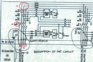
Fig. 2: Genset wiring to the MSB
There are three issues with this modification of the IT that have not been considered:
1,The Gensets windings are connected in Delta for a 3-wire network, and no neutral is fitted (Fig. 3:).
2. The windings can be changed to a Star configuration, and,
3. A neutral conductor can then be installed and run to the MSB.

Fig. 3: Genset windings – Delta configuration
With a genset neutral conductor installed, this will need to be connected to the 4th pole of the MCCB, as shown in Fig. 2. Unfortunately, there are a series of blunders that have not been recognised as follows:-
- The drawing (Fig 2:) shows that the incoming neutral looks like a spare contact on the MCCB. This is an axillary contact only and is used for the interlocking system to prevent a second supply from being placed in the non-synchronised MSB.
- The contactor is only 3-pole and would require the contactor to be changed out for a 4-pole model (Fig. 4:).
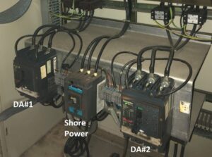
Fig. 4: MSB incoming power supplies to 3-pole contactors
- The MSB is not fitted with a neutral busbar for the distribution network and would require significant modification to fit this into the existing MSB.
- The 220-volt supply is transformed from the 380-volt network, and there has been no design consideration of decommissioning the 380/220-volt transformer and how to establish a neutral conductor in the 220-volt network (Fig. 5:).
- The earth lamp testing circuit should have been removed if the 380-volt network was modified to a TN-S network (by adding a neutral). Leaving this test arrangement in the circuit would create a circuit fault and trip RCDs whenever the test button is depressed (Fig. 5:).
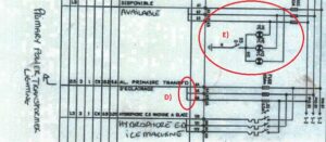
Fig. 5: MSB 380-volt Distribution
- The earth lamp testing circuit should not have been removed if the 220-volt network, as identified in point E), the stepdown transformer is a 3-wire arrangement to the primary and secondary windings.
- The 220-volt distribution is an IT network with no neutral fitted, and a first fault indication warning is required (Fig. 6:). From the drawing, it appears that this circuit is to be removed.
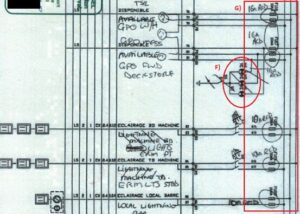
Fig. 6: MSB 220-volt Distribution
- This installation of RCDs (or RCBOs) to a 3-wire will never trip because an imbalance between the active and neutral needs to be energised in the RCD’s trip coil. There is no neutral in a 3-wire as all conductors are energised are 110-volts
RCD / RCBO
Understanding why RCD/RCBO devices will not trip on a delta-wired 220Vac Transformer requires some explanation. This circuit distribution is still a 3-phase network; voltages between phases are 220V, with the potential to earth of 110V.
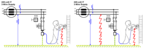
Fig. 7: First Fault Fig. 8 Second Fault
Figure 7 shows the first fault; the person is isolated, so there is no circuit. However, the earth monitoring alarm (See Section—Insulation Monitoring Device below) will go into alarm, warning of an earth fault. If there is a second fault (Fig. 8:), this will create a circuit that will conduct through the person. The RCD will not trip in a 3-wire IT network, as there will be no imbalance between the two active conductors. But conductors will continue to supply 110 volts. This is a critical oversight by the AMS, who undertook the review and circuit changes and approved the design.
Insulation Monitoring Device
The OEM of these devices requires the device to be fitted directly to the 380V 3-wire Delta distribution system busbar, but the Electrician did not read the installation instructions and chose to place a 4-amp MCB between the device and the phases (Refer to Fig. 9). The issue with this arrangement is that the 4-amp MSB could trip with a First Fault, and monitoring will be lost.
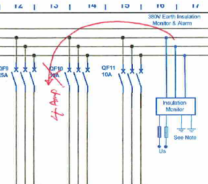
Fig. 9: Insulation Monitoring Device Installation
The electrical schematics also detailed a second insulation monitoring device to be installed on the 220V network. Again, it was decided that it was not required and considered that the network was a 4-wire Star (with a neutral) distribution system.
Not realising that the 220V network was a 3-phase distribution supplied by a step-down transformer from the 380V busbar.
Shore Connection Arrangement
The shore connection circuit arrangement shown in Figure 10 is a simple installation. It comprises a manual phase rotation switch (note that there is no indication device for phase rotation) and manually selected electrical interlocks for the shore power and the gensets.
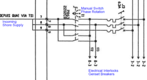
Fig. 10: Shore Supply
The incoming shore supply was wired to the vessel’s power distribution, with the three active and earthing of the vessel’s electrical installations. The neutral was not connected and was terminated. At some point, it was discovered that the Insulation Monitoring Device was reading 0Ω.
Once again, the Electrician failed to understand that the vessel was an IT network system, connected the 3-phase (no neutral), and energised the system.
Case 2. 12m Fibre Glass Fishing Boat
Recently, this boat owner contacted me concerning galvanic corrosion on his 3-month-old vessel. As part of the review, AMS-approved schematics were provided to help in tracking down the cause. In the end, it was found that the galvanic isolator had been fitted incorrectly. However, during the review, some serious faults were found in the schematics (Fig. 11), particularly in the protective earthing network.
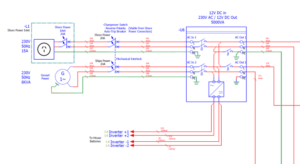
Fig: 11: AC Circuit Diagram
The first safety feature noted was that the fiberglass boat hull had no earthing plate. I informed the electrical contractor of the need for this plate, as detailed in the AS/NZS 3004.2, as it would be an earth plate complying with Clause 7 .1.2 in such a manner that it will always ensure an immediate discharge of electrical energy without danger. The installation had all the protective earth running back to the casing of the inverter, which was isolated from the sea (no earthing plate). The contractor’s response was that the installation was an above-earth system and did not require this plate.
The contractor’s dearth of knowledge about the differences in circuit design between an IT network and a TN-S network was evident. What is also evident is that the AMS, who had undertaken the review and approval of the installation circuit arrangement, had not noticed the serious failure in the design of not having an earthing plate.
There were also issues with lithium battery installation not making the minimum requirements as detailed in AS/NZS 3004.2.
I have gone into detail of the safety issues of the battery installation in another article which you are welcome to read, however one important point is that the inverter casing earth cable is to be connected directly to the earthing plate. This PE cable will be the same size (or the next size down), as that of the positive and negative DC cables and was not fitted.
Summary
The knowledge exhibited in the above 2 cases show that there is a lack of understanding of the functional safety requirements for an above earth electrical installation. The basic step is:-
- Insulation Monitoring Device needs to be fitted.
- 2 Devices required for a 3-wire network installation (transformed 220V)
- 1 Device required for a 4-wire network installation (400/220V)
Note: a device must be fitted to limit the voltage so the neutral can supply and reach the Earth for a 4-wire network.
- The insulation monitoring device are to alarm at the first earth fault
- RCDs will not trip in a 3-wire IT network
- RCDs will trip in a 4-wire IT network (but only after the second earth fault).
- Use of electrical hand tools and appliances in IT networks: An insolation transformer is recommended to provide additional protection.
I hope to instil in readers the importance of being aware of the type of electrical system installed. This would be most relevant to transitional vessels, as there may not be any drawings or modifications that have been undertaken that no longer reflect the vessel installation. Generally, I recommend an inspection before approving electrical installation drawings as AMS for supplied schematics for a transitional vessel.
Finally with relation to the second case study of the fibre glass hull vessel with no earthing plate and the network set up s as TN-S and thinking that this was suitable as an IT network, as the protective earth conductor was above earth. This can be seen as a complete failure of the electrical safety in the design, approval, installation, and the initial survey.