
Is the Polarity-Testing Device Fitted to your Boat or RV Electrically Safe?
Mark Smith CEng, CMarEng, FIMarEST, BAppSc(MarEng) Engineering Surveyor Accredited Marine Surveyor: AMSA – 3242-6148 4 Qld EC lic. 73995 Authorised Maritime NZ Surveyor – SRV242
On the surface, the devices available on the market will all check that the polarity of the conductors is correct; however, these devices check different wiring configurations to achieve the polarity.
First, let’s start with the basics and explain exactly what electrical safety means. To help define this phrase, we’ll look at an example that the Queensland Government has legislated:
Electrically safe means, for electrical equipment or an electrical installation, that all persons and property are free from electrical risk from the equipment or installation.
This wording is similar for all Australian Jurisdictions concerning electrical safety, in that there should be no risk of electrocution or fire to persons or property. These legislative Acts reference Standards for guidance to ensure electrical safety. For Polarity-Testing Device, this guidance is detailed within AS/NZS 3004.2 – Electrical installations; Part 2: Boat installations; Clause 3.5.3.2 Protection against reversal of polarity and states:
“……. a means shall be provided for checking the incoming supply’s polarity (active to neutral).
Such means shall include-
- an interlocking device with visual indication such that the shore supply cannot be connected if the polarity is incorrect; or
- an automatic correction device with a visual indication matching the shore supply’s polarity to the boat’s.
Yes, your first reaction is correct; it is vague in how a polarity checking device will be achieved. Additionally, the equipment is to be tested to ensure compliance with relevant standards. So, you cannot look at a clause in isolation and rely solely on this one point; you need to reference other relevant Standards. In this case, AS/NZS 3000 – Wiring Rules and AS/NZS 3017 – Electrical installations—Verification guidelines will provide additional guidance.
Let’s now identify the guidelines for test procedure methods of testing polarity (AS/NZS 3017) and detail the test procedure of polarity for a single pole switch using a voltage indicator with a power supply available. There are three main points to be taken from this:
- Connect one test lead to a known earth.
Note: Earthing continuity will have been established, and the MEN connection is intact.
- Make contact with other test leads to the active neutral terminal (one at a time).
- Disconnect both test leads.
This indicates that the polarity testing device has no permanent wired connection between the active and earth or the neutral and earth.
The other safety considerations that also need to be referenced for electrical safety are AS/NZS 3000:
- A circuit comprises live conductors only (clause 1.4.29) and has a difference of potential from the neutral or earthed conductor (clause 1.4.5).
- MEN (Multiple Earth Neutral), also known as a PEN (Protective Earth Neutral). There SHALL be a single conductor to combine the neutral and protective earth functions (clause 1.4.99),
- An earthing conductor, other than a main earthing conductor,
- Protective earthing conductor intended to carry earth fault currents only (clause 1.4.100),
- Testing is to prevent protective earthing conductors carrying current under normal conditions of operation, Clause 8.3.7.2 [e]) and,
- No protective earthing conductor is connected in parallel with any neutral conductor (Clause 8.3.7.2 [f]).
Lastly, the device is to be failsafe, and this is detailed within the legislation for each State and Territory. It is defined as electrical equipment or an installation where all persons and property are free from electrical risk.
Summary of Functionality
To simplify these clauses into quantifiable terms, these can be distilled down to 6 main identifiable points that a polarity testing device shall comply with to meet the Legislation and Standards:
| OUTCOME REQUIRED | STANDARD-CLAUSE | |
| 1) | Polarity testing is to be a momentary test. | 3017-3.3.3 |
| 2) | There is no connection between the neutral and earth conductors other than that at the MEN. | 3000-1.4.99 |
| 3) | There is no connecting circuit between the active and earth conductors. | 3000-1.4.5&29 |
| 4) | The earthing conductor is not to carry current, other than in a fault situation. | 3000-1.4.100 |
| 5) | An interlocking device to prevent connection. | 3004.2-3.5.3.2 |
| 6) | The device must be fail-safe. | Legislation-ACT |
Polarity Testing Devices Required Outcomes
There are four types of polarity testing devices available on the market. I have reviewed and tested these to determine if they meet the fundamental safety feature of eliminating electrical risk against the six main required outcomes, as listed above.
- Polarity Indication Lights
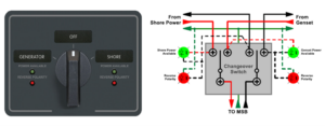
Fig: 1 – AC Rotary Switch Panel and Circuit Arrangement
The device is a simple indicator system, using diodes (LEDs) to block AC and allow only DC to pass. When the polarity is correct, the Green LED will illuminate, and if not, the Red LED will illuminate.
The review has shown that the six items for required compliance and safety were not met.
| OUTCOMES REQUIRED | STANDARD | MEETS | |
| 1) | Polarity testing is to be a momentary test.
The device is not testing and continually monitors the circuit polarity through a circuit connection between active/earth and neutral/earth. |
3017-3.3.3 | NO |
| 2) | There is no connection between the neutral and earth conductors other than that at the MEN.
The device creates a second PEN connection to show the incorrect polarity. |
3000-1.4.99 | NO |
| 3) | There is no connecting circuit between the active and earth conductors.
The device creates a circuit between the active and earth conductors to show that power is available. |
3000-1.4.5&29 | NO |
| 4) | The earthing conductor is not to carry current, other than in a fault situation.
The device’s indicator lights circuit arrangement, which is connected to the earth, allows current to be carried. Also, as the indicator lights are LED, these are working as a half-wave rectifier. This would mean DC voltage is being passed into the bonded earthing system (see note at end of article) |
3000-1.4.100 | NO |
| 5) | An interlocking device to prevent connection.
The device does not prevent connection if the polarity is incorrect and relies upon the operator not to connect in these circumstances. |
3004.2-3.5.3.2 | NO |
| 6) | The device must be fail-safe.
The device does not prevent connection if the indicator light circuits fail. |
Legislation-ACT | NO |
- MCB – Double pole (incl. Shunt trip coil)
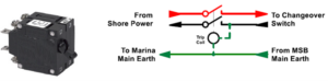
Fig: 2 – MCB and Circuit Arrangement
The MCB is a magnetic over-current trip device fitted with a trip coil. If the active and neutral conductors have been transposed, the trip coil will trip, opening the MCB.
The review has shown that three out of the six items for required compliance and safety were met.
| OUTCOMES REQUIRED | STANDARD | MEETS | |
| 1) | Polarity testing is to be a momentary test.
The device is not testing and continually monitors the circuit polarity between neutral/earth. |
3017-3.3.3 | NO |
| 2) | There is no connection between the neutral and earth conductors other than that at the MEN.
The device creates a second PEN connection to show the incorrect polarity. |
3000-1.4.99 | NO |
| 3) | There is no connecting circuit between the active and earth conductors.
The device does not create a circuit between the active and earth conductors. |
3000-1.4.5&29 | YES |
| 4) | The earthing conductor is not to carry current, other than in a fault situation.
The devices will only momentarily carry current in the earthing conductor to trip the breaker. |
3000-1.4.100 | YES |
| 5) | An interlocking device to prevent connection.
The device prevents connection if the polarity is incorrect. |
3004.2-3.5.3.2 | YES |
| 6) | The device must be fail-safe.
The device does not prevent connection if any part of the trip coil circuits fails. |
Legislation-ACT | NO |
- Polarity Monitoring Device
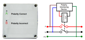
Fig: 3 – PMD and Circuit Arrangement
The PMD is a monitoring device, not a testing device. The active and Neutral Conductors are permanently connected. If the active and neutral conductors are transposed, the contactor’s coil will not energise.
The review has shown that four out of the six items for required compliance and safety were met.
| OUTCOMES REQUIRED | STANDARD | MEETS | |
| 1) | Polarity testing is to be a momentary test.
The device is not testing and continually monitors the circuit polarity between neutral/earth. |
3017-3.3.3 | NO |
| 2) | There is no connection between the neutral and earth conductors other than that at the MEN.
The device creates a second PEN connection to show the incorrect polarity. |
3000-1.4.99 | NO |
| 3) | There is no connecting circuit between the active and earth conductor.
The device creates a circuit between the active and earth conductors to show that power is correct. |
3000-1.4.5&29 | NO |
| 4) | The earthing conductor is not to carry current, other than in a fault situation.
The device’s circuit arrangement, connected to the earth, allows current to be carried. Also, as the indicator lights are LED, these are working as a half-wave rectifier. This would mean that a DC voltage is being passed into the bonded earthing system |
3000-1.4.100 | NO |
| 5) | An interlocking device to prevent connection.
The device prevents connection if the polarity is incorrect. |
3004.2-3.5.3.2 | YES |
| 6) | The device must be fail-safe.
The device prevents connection if any part of the device’s circuits fails. |
Legislation-ACT | YES |
- Residual Voltage ELCB
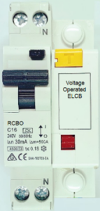

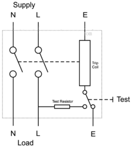
Simplified Circuit Arrangement
This device, ELCB, is a voltage-operated safety tripping device that detects a rise in potential between the protected interconnected metalwork (equipment frames, conduits, enclosures) and a distant isolated Earth reference electrode. It operates at a detected potential of around 50 volts to open a main breaker and isolate the supply from the protected premises.
However, this device has been adapted so that once a voltage potential is detected between the neutral and protective earth, it creates a short circuit to trip the RCBO.
These were first introduced about sixty years ago, and some problems have been associated with ELCB used in this application:
- Without a proper earth connection, the ELCB will not work. If the wire attached to the earthed rod is loose or broken, then the ELCB would not be able to sense the potentially hazardous voltage on the metallic body of the electrical/electronic device.
- ELCB is attached between the earthed wire and the metallic body of the electrical appliances. However, many other parallel paths exist for the currents to flow from the connected device body to earth without going through an earthed wire. For example, many metallic structures can provide a parallel path for the current to flow towards the earth. In this way, sometimes ELCB cannot detect the hazardous voltage on the metallic body of the device, which may cause serious injury.
The review has shown that two out of the six items for required compliance and safety were met.
| OUTCOMES REQUIRED | STANDARD | MEETS | |
| 1) | Polarity testing is to be a momentary test.
The device is not testing and continually monitors the circuit polarity between neutral/earth. |
3017-3.3.3 | NO |
| 2) | There is no connection between the neutral and earth conductors other than that at the MEN.
The device creates a second PEN connection to show the incorrect polarity. |
3000-1.4.99 | NO |
| 3) | There is no connecting circuit between the active and earth conductor.
The device creates a circuit between the active and earth conductors to show that power is correct. |
3000-1.4.5&29 | YES |
| 4) | The earthing conductor is not to carry current, other than in a fault situation.
The device’s circuit arrangement, connected to the earth, allows current to be carried. Also, as the indicator lights are LED, these are working as a half-wave rectifier. This would mean DC voltage is being passed into the bonded earthing system (see note at end of article) |
3000-1.4.100 | NO |
| 5) | An interlocking device to prevent connection.
The device prevents connection if the polarity is incorrect. |
3004.2-3.5.3.2 | YES |
| 6) | The device must be fail-safe.
The device prevents connection if any part of the device’s circuits fails. |
Legislation-ACT | NO |
ESHORE is the only device that meets all 6 requirements.