

Electrolysis and how to avoid it
ARTICLE: Electrolysis and how to avoid it
By Mark Smith
CEng, CMarEng, FIMarEST, BAppSc(MarEng)
Engineering Surveyor
Accredited Marine Surveyor: AMSA – 3242-6148 4
Qld EC lic. 73995
Based in Brisbane, Australia, Mark Smith is an AMSA Accredited Marine Surveyor, qualified electrician, and a Chartered Marine Engineer with over 40 years’ experience. Mark is a member of the Australasian Institute of Marine Surveyors, and Fellow of the Institute of Marine Engineering, Science and Technology (IMarEST). Mark is the owner of SET Maritime & Electrical, designer of the revolutionary new shore connection device – ESHORE.
Some boat owners, it seems, are completely unaware that electrolysis is something they need to be highly alert to. For more seasoned boaties, the words ‘electrolysis’ and ‘corrosion’ send shivers down the spine.
From my experience, most people don’t have a good understanding as to what electrolysis is, what causes it, and how to avoid it.
What is electrolysis?
As you would expect, seawater is a strong corrosive to metals, as it makes an excellent electrolyte.
Put simply, electrolysis occurs when an electrical current passes through water. That in turn causes a chemical reaction. In terms of boating, the electrolytic reaction occurs between two dissimilar metals – where the electrical current strips away one metal and deposits it on another causing the lesser of these to corrode.
What happens when you connect to shore power
When you connect your boat to shore power, the electrical installation’s earthing system is now common with the marina’s earthing system. As all your boat’s metallic components are earthed (hull, skin fittings and propulsion systems), these are now connected to the shore earth grounding system. This also means that your boat has a common connection with adjacent boats that are connected to shore power.
Why is it a problem?
The sacrificial anodes that protect the metal hull, propulsion and steering systems of your boat will deplete – and in a 12 month period approximately 50% will be consumed. This will protect your boat from dissimilar metals electrolysis.
An induced DC voltage will increase the rate of depletion of the sacrificial anodes and once this protection is gone, it will start to eat away other underwater metal components. In particularly bad cases (like a DC earth fault), can lead to irreparable damage to propellers and shafting in a matter of a few weeks.
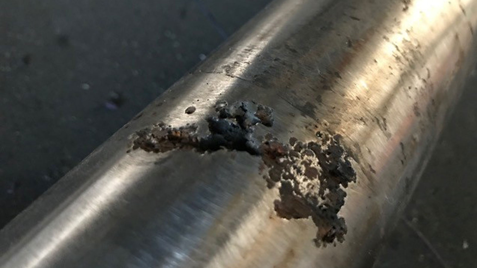

Electrolysis of Shafting
What you need to do
As this is all happening all under the water, you will not notice anything out of the ordinary. However when you slip your pride and joy, it will be obvious – and too late. But there are a couple of things that you can do:
- Grab your mask and snorkel to take a dive and have a look at the sacrificial anodes to gauge the rate of depletion.
- Test for Voltage and Current being conducted in the Protective Earth (PE).
NOTE: This requires the PE to be broken and metering being connected to take such reading for DC and AC. This can only be undertaken by a Licenced Electrical Contractor.
As electrolysis is a naturally occurring chemical reaction, the upkeep of sacrificial anodes is very important to ensure that items like the metal hulls, propulsion and steering systems dont fizz away.
The other is the fitting of a galvanic isolator, which will impede the voltage through the PE generated by the galvanic isolator.
NOTE: The protection that a galvanic isolator provides is 1.4Vdc, which is above the voltage range generated by the electrolysis of dissimilar metals. If a DC voltage exceeds this 1.4Vdc threshold, say from a DC system to earth fault from your neighbour’s boat. Then the galvanic isolator will not prevent the circuit from being created.
Getting technical
When a potential voltage difference is present, a chemical reaction occurs, and a current will flow between these dissimilar metals. The more noble material will become the cathode and the more base material will be the anode. This reaction will strip away metal from anode and deposit it on cathode. The migration of metal is caused by the electron flow and is opposite to the current flow.
The below table is an extract from the galvanic series and shows their electrochemical voltage range relative activity in seawater.
Table 1: Galvanic series
| MATERIAL | VOLT RANGE | |
| Noble (Cathodic) | Graphite | 0.36 to 0.19 |
| Titanium | 0.04 to -0.12 | |
| Stainless Steel (316) | 0.00 to -0.10 | |
| Nickel Copper Alloys | -0.02 to -0.13 | |
| Stainless Steel (304) | -0.05 to -0.13 | |
| 70/30 Copper/Nickel | -0.14 to- 0.25 | |
| 90/10 Copper/Nickel | -0.14 to- 0.27 | |
| Admiralty Brass | -0.24 to -0.37 | |
| Copper | -0.31 to -0.40 | |
| Aluminium Bronze | -0.31 to -0.48 | |
| Cast Iron | -0.58 to 0.71 | |
| Mild Steel | -0.58 to 0.71 | |
| Aluminium Alloy | -0.76 to -0.99 | |
| Zinc | -1.00 to -1.07 | |
| Base (Anodic) | Indium Aluminium Alloy | -1.10 to -1.25 |
To offset this type of corrosion the fitting of sacrificial anodes to hull is done to protect your boat’s metallic components from corroding away. But it is worth remembering that the larger the potential voltage difference between dissimilar metals, the more rapidly the anode will corrode.
Figure 1: The process of the chemical reaction between cathodes and anodes.

Once the anode has been exhausted by the chemical reaction, then the next base metal on the galvanic series will become anodic.
Having briefly described the process of electrolysis, it’s important to understand what happens when your boat is connected to the marina’s shore power.
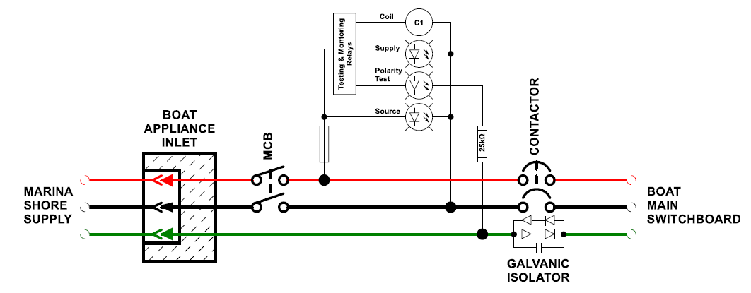
Figure 2: How a circuit is formed between boats at adjacent berths

This circuit is easily preventable by the fitting of a galvanic isolator to the earthing system of your boat. The device is fitted between the boat’s main earth and the protective earth (PE) at the shore connection arrangement.
This prevents a circuit forming, allowing low voltage DC currents circulating between berthed boats underwater metals, via the marina’s common AC earthing conductor as below.
Figure 3: Low voltage DC currents circulating between berthed boats underwater metals
The construction of a galvanic isolator has two pairs of diodes set up so that a voltage greater than 1.2 volts is required to cause them to conduct and create a circuit. This is known as the breakthrough voltage of the diode.
If there is AC leakage on the shore power PE and voltage is greater than 1.2Vac, the leakage will ‘bias’ the diodes into a conductive state (breakthrough voltage). When biased open the galvanic isolator will provide any protection from electrolysis. In other words, the device may as well not be fitted, and research has shown that voltages above 1.9Vac is sufficient to render the isolator ineffective.

To prevent rendering the isolator ineffective, a capacitor is fitted to the galvanic isolator and has the function of allowing any AC leakage current to bypass the diodes. By not biasing the diodes into a conductive state it allows the AC currents to be conducted safely to earth via the PE. This arrangement does not affect the blocking action of the galvanic isolator for DC currents preventing electrolysis of dissimilar metals.
However, you need to be aware that the device’s capacitor will have a current-carrying limit and are generally less than 8 amps. If this capacity is exceeded, then the AC leakage will bias the diodes into conductive state, voiding the galvanic isolation of the device. This situation also is potentially lethal, however the shoreside RCD rated at 30 milliamps will trip.
A galvanic isolator should not block stray AC currents, and only block galvanically generated DC currents. It should be understood that DC earth faults from the boat’s DC electrical installation will be, in general terms, greater than 1.2Vdc. This will bias the diodes into conductive state earth fault DC voltage conduct through the PE system, rendering the isolator ineffective.
Galvanic isolator devices use diodes that are ‘fail safe’ type. The purpose of this type of diodes is that if they fail, they fail to a close circuit. This is to ensure the continuity of the PE conductor is maintained. Older devices, the diodes can be a type that fail to an open circuit and will lead to a potentially lethal situation with the PE conductor open circuited.
Lastly, Galvanic isolators are to meet compliance as detailed within AS/NZS 3004.2 for boats, shall be designed and tested to comply with ABYC Standard A-28.
Where galvanic isolators are intended to be used on a 50 Hz shore power supply, the A-28 compliance tests must be carried out with an AC test voltage of 230 v at 50 Hz and consists of the following test:
- AC Conductivity Test
- Galvanic Current Blocking Test
- Galvanic Current Blocking Test with AC Superimposed
- Vibration Test
- Shock Test
- Temperature Test
- Short Circuit Test
- Galvanic Isolator Fail Safe Test
- Torque & Strain Relief Test
Click here for more articles on marine electrical safety.
If you have any questions, please get in touch